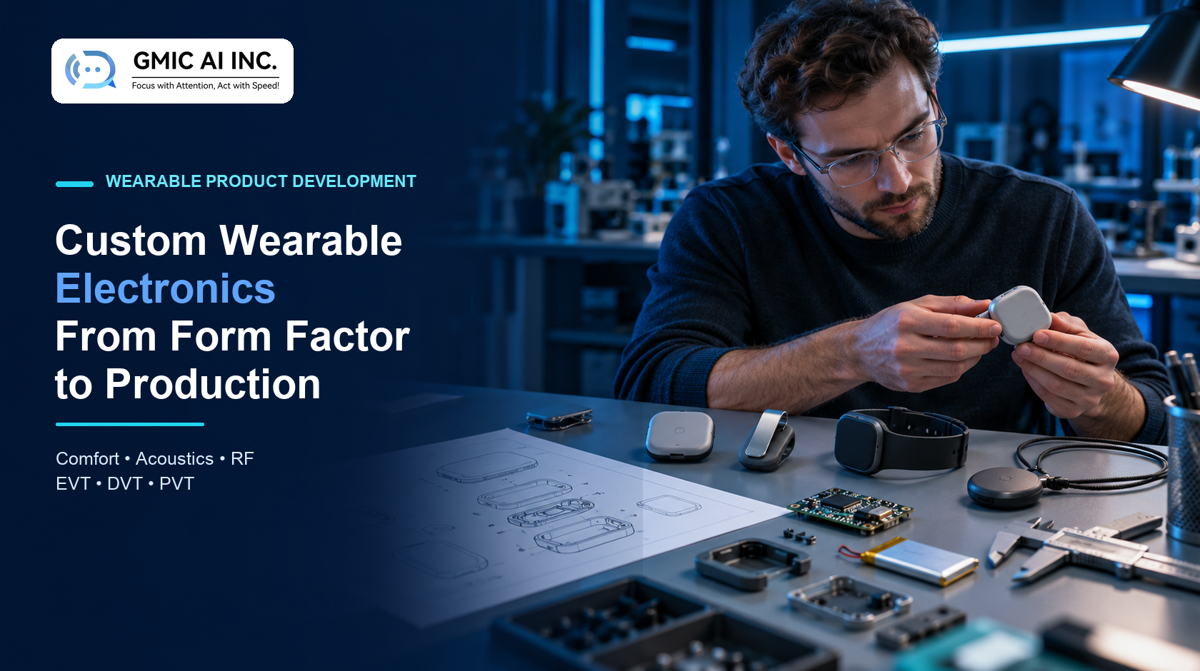
Custom wearable electronics are not simply compact circuit boards inside smaller enclosures. A viable wearable must balance comfort, placement, acoustics, antenna performance, battery capacity, thermal behavior, controls, cleaning, assembly and regulatory constraints. Changing one dimension can affect several others.
In brief: Start with the user, task and wear location. Convert those observations into measurable product requirements. Prove the highest-risk interactions with form studies and engineering prototypes before locking tooling, then carry the evidence through EVT, DVT, PVT and production.
Explore GMIC AI wearable device development or discuss a custom wearable project.
What Counts as Custom Wearable Electronics?
Custom wearable electronics combine purpose-built hardware, firmware and industrial design for a specific workflow. Common forms include:
- Badges and ID-card-style devices.
- Pendants and neck-worn recorders.
- Lapel clips and body-worn microphones.
- Wrist-worn devices.
- Head-worn audio or sensing products.
- Body patches and sensor modules.
- Belt, pocket or garment-mounted devices.
Customization can include the enclosure, attachment method, microphone geometry, antenna, PCB, sensors, battery, charging, firmware, companion application, branding and manufacturing test process. The correct scope depends on what is already proven and what creates product differentiation.
Begin With the Wear Scenario, Not the Enclosure
A useful product specification describes the complete use context:
- Who wears, charges, cleans and services the device?
- Where on the body or clothing is it placed?
- How long is each session and each working day?
- Is the user standing, driving, walking or wearing protective equipment?
- What feedback confirms recording, connection, battery and errors?
- What happens when the device is dropped, covered, rotated or removed?
- Which data must remain available when a phone or network is unavailable?
For medical products, the FDA frames human factors around intended users, uses, use environments and the complete user interface. Its examples explicitly include the size and shape of handheld and wearable devices. That same discipline is valuable for non-medical wearables even when medical-device rules do not apply.
Choose the Form Factor With a Trade-Off Matrix
| Form factor | Strengths | Design risks to test early |
|---|---|---|
| Badge | Familiar placement, visible status area, room for controls | Rotation, clothing movement, weight and clip leverage |
| Pendant | Flexible clothing compatibility, simple donning | Swing, cord safety, microphone movement and orientation |
| Lapel clip | Good voice proximity, discreet | Small battery, fabric variability, occlusion and handling noise |
| Wrist | Frequent visual access, established charging behavior | Voice distance, wrist motion, skin contact and antenna detuning |
| Head-worn | Consistent microphone geometry | Comfort, hygiene, social acceptance and mechanical fatigue |
| Patch/module | Stable sensing location, low visual profile | Adhesive/skin interface, sealing, removal and disposable components |
Score candidate concepts against measurable criteria such as mass, center of gravity, audio signal quality, radio link margin, estimated runtime, accessible control area, assembly time and cleanability. A beautiful concept with no engineering margin is not a production design.
Comfort Is an Engineering Requirement
Comfort should be evaluated over realistic durations, not only during a short design review. Important variables include:
- Total mass and how that mass is distributed.
- Pressure points and contact area.
- Edge radius, surface finish and local heat.
- Movement, bounce and garment pull.
- Interaction with hair, jewelry, PPE and other devices.
- One-handed attachment and removal.
- Accessibility for users with limited dexterity or vision.
Translate findings into requirements: maximum device mass, allowed surface temperature rise, attachment force range, minimum control dimensions and acceptable movement during defined activities. Record participant profile, clothing, task, duration and prototype revision so the evidence remains useful.
Acoustic Placement for Voice Wearables
For a voice wearable, microphone performance depends on the complete mechanical system. Port size, membrane, mesh, adhesive, gasket, cavity and enclosure wall can change frequency response and sensitivity. Clothing can cover a port; fingers can create handling noise; movement can generate low-frequency energy.
Prototype the production-intent acoustic stack and test:
- Multiple speakers, distances and orientations.
- Quiet rooms, vehicles, outdoor wind and workplace noise.
- Clothing and attachment variations.
- Port occlusion and partial blockage.
- Handling, tapping and garment-rub noise.
- Sealed, vented and water-resistant configurations.
The result should connect physical design to application metrics. For a transcription product, that can include word error rate and task-level accuracy alongside electroacoustic measurements. See AI audio front-end design and wearable transcription accuracy testing.
Antenna Placement and the Human Body
The body, battery, display, metal clip, shielding and enclosure materials can change antenna tuning and efficiency. Do not approve antenna performance on a bare development board and assume it will survive packaging.
Evaluate the assembled device in representative worn positions. Include weak-signal operation, rotation, hand contact and different clothing. Preserve antenna keep-out regions and control changes to nearby materials and fasteners.
Wireless products placed on or near the body also need market-specific equipment authorization and RF-exposure planning. FCC guidance identifies RF-exposure requirements and procedures for portable and mobile devices, while Bluetooth and Wi-Fi transmitters are subject to the applicable equipment-authorization rules. Engage a qualified test laboratory early; the exact route depends on the radio, use distance, region and final configuration.
Battery, Charging and Thermal Design
Runtime begins with a measured operating profile rather than a battery label. Define time in sleep, connected idle, capture, processing, transfer, user feedback and update states. Then measure production-intent hardware.
Battery capacity affects thickness and mass. Charging architecture affects sealing, accessories and user behavior. Processing and radios create heat that must be evaluated at the skin or garment interface. Plan for:
- Peak current and voltage-drop margin.
- Battery protection and fuel-gauge behavior.
- Charging time and safe charging temperature.
- Connector, dock or wireless-charging alignment.
- Degraded battery capacity over the intended service life.
- Shipping, storage and deeply discharged recovery.
- Fault states, including blocked vents or repeated reconnects.
Claims such as “all-day” should be tied to a documented workload, configuration, battery age and environmental range.
Controls, Feedback and Failure Recovery
A wearable often communicates with a small number of buttons, LEDs, tones or haptics. Each indication should map to a user decision. Avoid making critical states distinguishable only by subtle color differences or short patterns that are difficult to remember.
Test whether users can answer:
- Is the device on and ready?
- Did recording start and stop?
- Is data saved, transferring or complete?
- Is the battery low or charging?
- Has pairing or authentication failed?
- What can the user do without a phone or network?
Design recovery at the same time as the ideal path. The firmware, mobile app and enclosure controls should tell one consistent story. See firmware integration for voice AI devices.
Cleaning, Sealing and Material Selection
Cleaning requirements affect coatings, labels, adhesives, seams, ports and connectors. Define the actual cleaning agent, method, frequency and exposure time before selecting materials. “Water resistant” and “cleanable” are different requirements.
Build coupons or representative assemblies to examine discoloration, cracking, swelling, loss of adhesion and marking legibility. If ingress protection is required, define the target and validate production-intent assemblies. A gasket design must also tolerate part variation, repeated assembly and compression set.
For skin-contacting, medical or safety-critical products, material and biocompatibility decisions require product-specific regulatory expertise. Avoid treating a generic supplier declaration as proof for the final use condition.
Design the Electronics and Enclosure Together
Sequential design—PCB first, enclosure later—often creates late compromises. Co-develop:
- Board outline, rigid-flex regions and connector access.
- Antenna and sensor keep-outs.
- Microphone ports and acoustic sealing.
- Battery support, swelling allowance and replacement strategy.
- Light pipes, buttons, haptics and displays.
- Fasteners, snaps, adhesives and weld joints.
- Programming, test and debug access.
- Assembly order, rework and service access.
Tolerance analysis should cover the full stack, not only individual dimensions. See GMIC’s custom hardware enclosure design guide.
Cybersecurity and Product Lifecycle
Connected wearables need a support model beyond launch. NIST IR 8259 Rev. 1 describes cybersecurity activities for IoT product manufacturers across product development and support, including understanding customer needs and communicating cybersecurity information. Translate that into product decisions such as:
- Unique device identity and secure provisioning.
- Protected credentials and debug interfaces.
- Signed firmware and recoverable updates.
- Data minimization and configurable retention.
- Vulnerability reporting and response.
- Defined support and end-of-life periods.
- Secure reset, ownership transfer and decommissioning.
The product includes its mobile app, cloud services and update infrastructure—not just the wearable enclosure.
Prototype in Layers
Use each prototype to answer named questions:
- Appearance model: size, visual language and stakeholder alignment.
- Ergonomic model: wear location, attachment, comfort and controls.
- Engineering mule: electronics, audio, radio, sensors and firmware.
- Integrated prototype: combined mechanical and electrical risks.
- Production-intent unit: tooling, materials, processes and test coverage.
Do not confuse a presentation model with verified engineering evidence. Keep a prototype matrix listing revision, build process, included functions, exclusions and required tests.
From EVT to DVT to PVT
| Phase | Main question | Typical wearable evidence |
|---|---|---|
| EVT | Does the architecture work? | Audio, radio, sensor, power, thermal and attachment feasibility |
| DVT | Does the design meet requirements? | Reliability, environmental, ingress, usability, compliance pre-scan and tolerance validation |
| PVT | Can the factory build it repeatedly? | Line process, fixtures, programming, calibration, yields and controlled work instructions |
Exit criteria should be agreed before each build. Track failures to root cause, corrective action and verification. Our EVT vs DVT vs PVT guide explains the decision gates in more detail.
Production Readiness Checklist
Before volume production, confirm that the team controls:
- Released BOM, drawings, Gerbers, firmware and test software.
- Approved materials, colors, textures and cosmetic limits.
- Supplier qualifications and critical component alternates.
- Assembly process, torque, adhesives, curing and sealing.
- Device identity, key injection and serialization.
- Audio, radio, sensor, charging and current tests.
- Calibration method, limits and traceability.
- Packaging, accessories, labeling and instructions.
- Reliability and compliance evidence for the final configuration.
- Change control, failure analysis and field-update process.
A golden sample is useful only when its revision, deviations and acceptance criteria are controlled.
How to Select a Custom Wearable Device Manufacturer
Ask potential partners to explain how they will manage the product’s coupled risks. Useful evidence includes:
- Relevant acoustic, RF, power and mechanical engineering capability.
- A clear prototype and verification plan.
- Supplier and tooling management.
- Firmware, mobile and cloud interface ownership.
- Manufacturing-test and traceability strategy.
- Compliance planning tied to target markets.
- Controlled documentation, configuration and change management.
- A transparent quotation with assumptions and exclusions.
The lowest unit-price estimate is not necessarily the lowest-risk program. Compare the completeness of scope, evidence and ownership. See the custom AI wearable ODM guide and AI hardware ODM/OEM services.
Frequently Asked Questions
How long does custom wearable development take?
It depends on architecture novelty, industrial design, firmware, applications, tooling, reliability testing, certification and supply-chain readiness. A schedule is credible only when assumptions, dependencies and exit criteria are visible.
Should a wearable use an off-the-shelf module or a custom PCB?
A module can reduce some RF and integration work, while a custom PCB may improve size, cost and placement. The decision should compare certification strategy, volume, lifecycle, antenna constraints, power and software support.
When should industrial design begin?
At program definition. Industrial design, mechanical engineering, RF, acoustics and electronics should iterate together before architecture and tooling are locked.
What should be tested before tooling?
Test the highest-risk assumptions: wear comfort, attachment, microphone geometry, antenna performance, battery and thermal behavior, controls, sealing strategy and assembly access. Tooling should refine a proven direction, not discover the basic product architecture.
Build the Evidence Before You Build the Volume
Successful custom wearable electronics come from disciplined trade-offs. Define the real wear scenario, convert it into measurable requirements, prototype the coupled mechanical and electrical risks, and preserve verification evidence through production.
Talk with GMIC about a custom wearable electronics program.
Sources
- FDA: Applying Human Factors and Usability Engineering to Medical Devices
- FDA: Human Factors Considerations
- FCC: Mobile and Portable Device RF Exposure and Equipment Authorization Procedures
- NIST IR 8259 Rev. 1: Foundational Cybersecurity Activities for IoT Product Manufacturers
Editorial note: Technical guidance reflects public sources available on October 23, 2026. Regulatory and certification requirements depend on product claims, markets and final configuration. Consult qualified laboratories and regulatory specialists for a specific device.