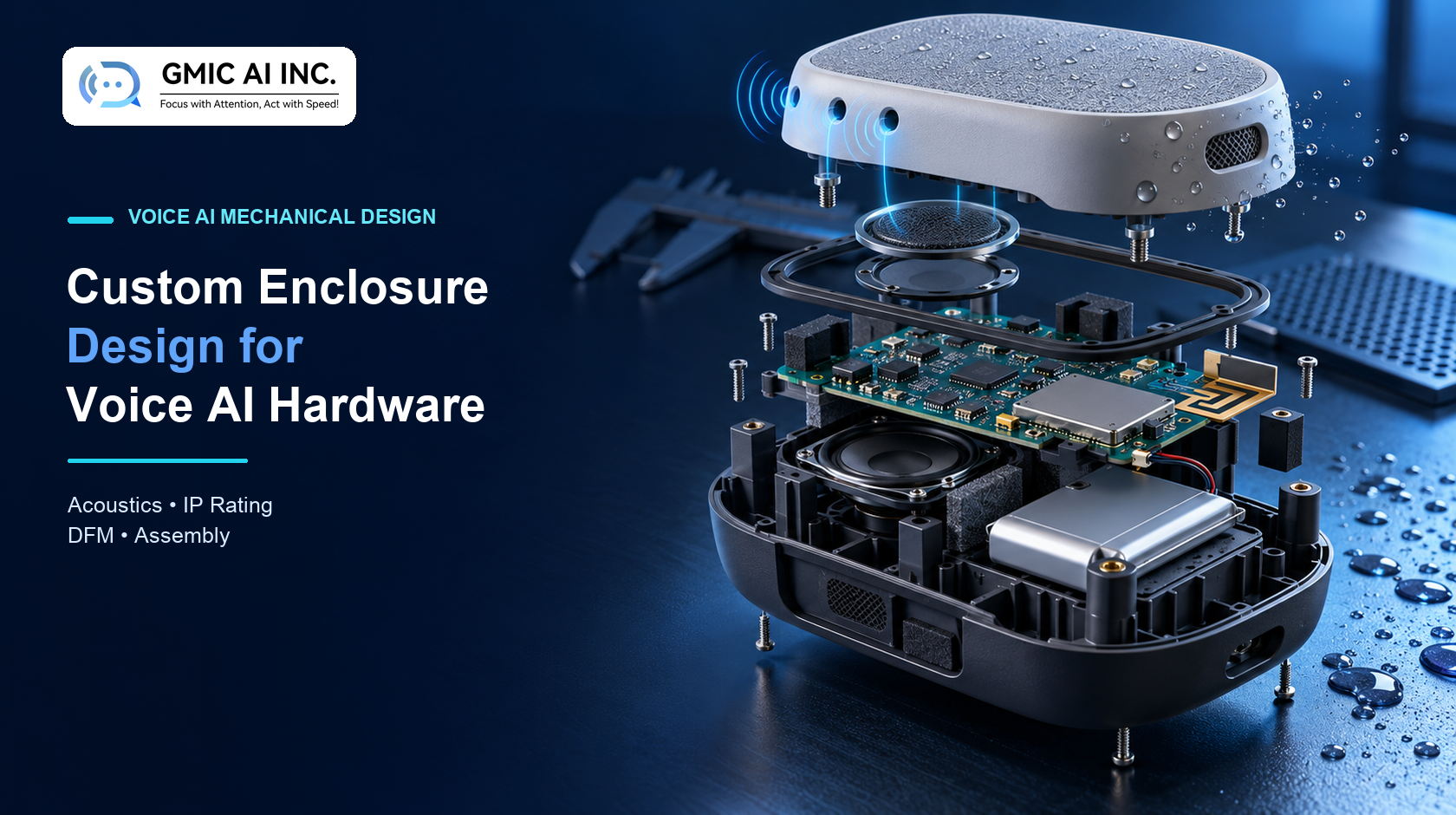
Custom enclosure design for voice AI hardware is a system-engineering task. The housing determines how sound reaches the microphones, how speaker energy returns as echo, how antennas radiate, how heat escapes, how water and dust are managed, and whether the factory can assemble the product repeatedly. An enclosure can look finished while still undermining the electronics and AI workflow inside it.
In brief: Freeze enclosure geometry only after the acoustic path, antenna region, thermal loads, sealing strategy, assembly sequence and molding constraints have been tested together. Define measurable requirements and verify them on production-intent materials before tooling approval.
Explore GMIC custom hardware enclosure design or discuss a voice AI hardware project.
What the Enclosure Must Do
A voice AI enclosure can have several simultaneous responsibilities:
- Position microphones, speakers, antennas, displays, buttons and sensors.
- Protect electronics against handling and the intended environment.
- Maintain acoustic paths and mechanical isolation.
- Control light leakage, vibration and user feedback.
- Support charging, connectors, service and updates.
- Provide acceptable surface temperature and heat flow.
- Enable reliable assembly, calibration and production testing.
- Express the brand without implying unverified performance.
These responsibilities compete. A tighter seal can increase acoustic insertion loss. A larger battery can crowd the antenna. A polished cosmetic surface can reveal sink marks from internal bosses. Design reviews should therefore include industrial design, mechanical, acoustic, RF, electronics, manufacturing and firmware owners.
Start With the Use Environment
Describe the real product context before drawing the shell:
- Handheld, wearable, tabletop, wall-mounted or vehicle-mounted?
- Near-field speech or voices across a room?
- Indoor office, clinic, factory, vehicle or outdoor use?
- Expected drops, vibration, cleaning agents and temperature range?
- Exposure to rain, splashes, dust, sweat or condensation?
- How often is it charged, attached, opened or serviced?
- Which surfaces are touched, seen and heard?
Translate those observations into testable requirements: maximum dimensions and mass, drop height and orientation, target ingress protection, microphone response tolerance, speaker output, radio performance, surface-temperature limit and assembly-time objective.
The Microphone Acoustic Path
For a MEMS microphone, sound may pass through an enclosure aperture, protective mesh or membrane, front cavity, gasket, PCB opening and package port. Every part of that path can shape frequency response.
Gore’s acoustic design guidance notes that the housing, acoustic vent, back cavity, PCB, microphone and compression foam interact as a system. It also explains that front- and back-cavity geometry and vent active area can affect insertion loss. Supplier recommendations are useful starting points, but the final product stack must be measured.
Control:
- Port diameter, length and edge condition.
- Alignment among housing, gasket, PCB and microphone.
- Cavity volume and leakage.
- Membrane or mesh type, active area and adhesive.
- Compression range and long-term set.
- Part tolerances and assembly shift.
- Contamination during molding, painting and assembly.
For a bottom-port microphone, the PCB hole is part of the acoustic channel. For a top-port microphone, the seal from the package to the housing still needs controlled compression and alignment.
Avoid Accidental Resonances
Long, narrow ports and cavities can introduce resonances or attenuation. The risk increases when a packaging constraint turns the acoustic path into a tube or when open volumes are connected by small apertures.
Evaluate the complete response rather than one frequency. Use sweeps, speech signals and application-level recordings. Compare nominal parts with tolerance extremes and partially blocked ports. If firmware equalization compensates for the enclosure, version the coefficients with the mechanical revision and verify that unit-to-unit variation remains within the correction range.
See AI audio front-end design and AI microphone hardware.
Speaker Cavities, Echo and Vibration
A voice product with playback must manage both desired output and unwanted coupling into the microphones. The speaker cavity, grille, seal and back volume influence output and distortion. Mechanical leakage or vibration can create paths that DSP cannot fully remove.
Microchip’s echo-tuning guidance recommends maximizing acoustic separation between speaker and microphone to support acoustic echo cancellation. In the final design, also examine:
- Direct airborne coupling.
- Structure-borne vibration through the enclosure and PCB.
- Speaker gasket compression and leakage.
- Grille blockage and cosmetic fabric.
- Enclosure buzz, rattle and loose cables.
- Reference-signal timing for AEC.
- Double-talk and maximum-volume conditions.
AEC is a system function. Good DSP does not excuse an avoidable mechanical coupling path.
Microphone Arrays Need Dimensional Control
Array performance depends on microphone position, orientation, matching and synchronization. Enclosure changes can alter spacing or create different acoustic paths for each channel.
Document the acoustic center and tolerance for every channel. Keep port geometries consistent when the algorithm assumes matching. Verify channel mapping in firmware and production test. A cosmetic hole pattern is not proof that every opening reaches a functional microphone.
Test arrays with the final housing, table or mounting surface, because reflections and boundary effects can change beam patterns. See microphone array and beamforming hardware.
IP Ratings Are Product-Level Claims
IEC 60529 defines degrees of protection provided by enclosures using the IP Code. The exact target, test conditions and applicable standard edition should be confirmed for the product and market.
An IP target applies to a defined final configuration—not to a gasket or membrane in isolation. The product-level result depends on:
- Housing joints, fasteners and welds.
- Connector, button, display and speaker openings.
- Acoustic vents and their installation.
- Gasket material, compression and surface finish.
- Part flatness, warp and tolerance stack.
- Pressure equalization and temperature changes.
- Damage after drop, aging, cleaning or service.
Do not describe a product as IP-rated before the representative configuration has passed the applicable test and the claim is properly documented.
Acoustic Vents Require a Trade-Off
An acoustic vent can help protect a microphone opening from contaminants while transmitting sound. Protection and acoustic transparency are not independent.
Gore’s design guide explains that membrane geometry, active area, front cavity, back cavity and installation affect acoustic performance. For any selected vent, verify:
- Insertion loss and frequency response in the assembled device.
- Behavior when wet, dirty or partially blocked.
- Adhesive compatibility and bond area.
- Compression, handling and automated placement.
- Environmental aging and cleaning exposure.
- Lot variation and supplier change control.
Use the vendor’s stated test configuration only for comparison. Product performance must be measured with the final aperture, cavity, microphone and assembly process.
Antenna Keep-Outs and Plastic Choices
Plastic is not electrically invisible. Resin, pigments, coatings, nearby fasteners, batteries, displays, cables and a user’s body can shift antenna tuning and efficiency. A conductive coating used for EMI control can also block the intended RF path.
Reserve the antenna volume early. Control nearby material and wall thickness. Test the fully assembled device in representative orientations and use conditions. For products used close to the body, include market-specific RF-exposure planning; FCC guidance identifies the applicable requirements and procedures for portable and mobile devices.
Do not rely solely on a module’s prior approval. The final antenna, enclosure, integration and operating conditions determine which evidence and authorization work applies.
Thermal Design Without Acoustic Compromise
Processors, radios, charging circuits and batteries generate heat. Enclosure material and internal layout determine where that heat goes. Sealing reduces airflow; acoustic openings should not become accidental thermal vents without analysis.
Build a power-state table covering idle, recording, processing, wireless transfer, charging, update and fault conditions. Measure component and touch temperatures under realistic ambient conditions. Consider:
- Heat spreading through PCB copper, frames or dedicated interfaces.
- Distance from microphones, batteries and skin-contact areas.
- Material conductivity and thickness.
- Solar load or enclosed vehicles where relevant.
- Dust, fabric or mounting surfaces that block convection.
- Performance throttling and user feedback.
Thermal simulations are useful, but validate them with instrumented prototypes and measured power.
Buttons, LEDs and Human Factors
Controls and indicators are part of the enclosure architecture. For a voice device, users must be able to understand recording, muted, connected, charging, low-battery and fault states.
Check button force, travel, tactile separation and one-handed use. Prevent accidental activation while wearing, carrying or cleaning the device. Evaluate LED visibility in bright and dark environments, through the final light pipe and surface finish. Do not use color as the only critical distinction when another cue is feasible.
For privacy-sensitive recording, the visible hardware state should agree with firmware and application state. A decorative LED that can disagree with actual capture creates avoidable risk.
DFM for Injection-Molded Enclosures
Design for manufacturability begins before tooling. Protolabs’ molding guidance emphasizes consistent wall thickness, draft, radii, and appropriately designed ribs and bosses to reduce sink, warp and ejection problems.
Wall thickness
Use a material- and geometry-appropriate nominal wall and keep transitions gradual. Thick local sections cool differently and can create sink, voids or dimensional change. Core out bulk and use ribs or gussets where appropriate.
Draft and texture
Vertical surfaces need draft for reliable ejection. Texture generally requires additional draft. Confirm the cosmetic specification, tooling direction and supplier process rather than applying a universal angle.
Ribs, bosses and fasteners
Ribs can add stiffness without a solid thick wall, but their intersections can telegraph sink onto cosmetic surfaces. Isolate and support screw bosses; account for insert installation, torque, creep and repeated service.
Parting lines, gates and ejectors
Place these with both function and appearance in mind. A gate can influence flow, knit lines and local stress. Ejector marks and flash limits should be shown on controlled drawings.
Undercuts and side actions
Undercuts can add tooling cost, maintenance and cycle complexity. Use them where they provide clear product value and confirm how the tool will release the feature.
General rules are not a substitute for the selected resin, mold flow, tool construction and molder review.
Assembly Strategy
Choose joining methods according to sealing, service, cosmetics, rework and volume:
| Method | Advantages | Risks to manage |
|---|---|---|
| Screws | Serviceable, controllable clamp load | Boss stress, torque variation, visible hardware |
| Snaps | Fast, no loose fasteners | Creep, stress whitening, difficult rework |
| Adhesive | Thin joints, sealing potential | Cure, surface preparation, squeeze-out, serviceability |
| Ultrasonic welding | Fast permanent joint | Part geometry, weld flash, acoustic-component exposure |
| Heat staking | Captive assembly, localized process | Permanent joint, process window, plastic damage |
Define assembly order before finalizing internal features. Verify tool access, cable routing, adhesive application, gasket retention, programming and test access. A housing that can be assembled once by an engineer may still be unsuitable for a production line.
Tolerance Stack and Sealing Compression
Analyze dimensions across the complete stack: molded shells, PCB, microphone height, gasket, membrane, battery and fasteners. Worst-case analysis should identify whether parts still fit, seals still compress and sensitive components avoid excessive load.
Dimension critical functions from stable datums. Avoid long chains through cosmetic surfaces. For gasketed joints, define the required compression window and confirm that housing stiffness and fastener placement maintain it after molding and aging.
Use metrology and functional tests together. A dimension can be within drawing tolerance while the assembled acoustic or sealing result still fails.
Prototype the Right Questions
Different processes answer different questions:
- Appearance model: visual proportions, color and surface language.
- Ergonomic prototype: grip, placement, attachment and controls.
- Acoustic mule: ports, gaskets, vents, speakers and arrays.
- RF/thermal prototype: representative materials and internal layout.
- Soft-tool or bridge build: molding behavior and assembly process.
- Production-intent build: final tooling, materials, finishes and controls.
Record what each prototype does not represent. A machined or printed part may differ from molded resin in stiffness, surface, tolerances and acoustic leakage.
See rapid AI hardware prototyping and hardware prototype validation.
Enclosure Verification Matrix
| Area | Evidence to collect |
|---|---|
| Acoustics | Frequency response, sensitivity, distortion, echo, rub and wind noise |
| Mechanical | Drop, vibration, fastener, attachment and connector durability |
| Environmental | Temperature, humidity, cleaning, sweat or UV as applicable |
| Ingress | Applicable dust/water test on representative final assemblies |
| RF | Antenna tuning, radiated performance, coexistence and exposure evidence |
| Thermal | Component and touch temperatures across power states |
| Usability | Controls, indicators, charging, cleaning and recovery tasks |
| Manufacturing | Dimensions, cosmetics, assembly time, yields and process capability |
Failures should link to root cause, corrective action, verification and affected revision. Do not close a mechanical issue with a note that the next build “looks better.”
Tooling Release Checklist
Before releasing production tooling, confirm:
- Industrial design surfaces and controlled CAD revision.
- Material, finish, color and marking specifications.
- Acoustic ports, cavities, vents and gasket stack.
- Antenna keep-outs and final nearby materials.
- Thermal interfaces and component clearances.
- Nominal walls, transitions, draft, ribs and bosses.
- Parting lines, gates, ejectors and allowed witness marks.
- Assembly order, tools, torque and adhesive processes.
- Critical dimensions, datums and tolerance analysis.
- Prototype evidence for the highest-risk functions.
- Verification plan and process for controlled tool changes.
Use a “steel-safe” or otherwise modifiable direction where appropriate, but do not treat future tool correction as the primary design strategy.
Frequently Asked Questions
Does an IP-rated vent make the whole enclosure IP-rated?
No. Product-level ingress performance depends on the complete enclosure, joints, openings, installation, tolerances and condition of the tested unit.
Can enclosure acoustics be fixed in DSP?
Some repeatable response shaping can be compensated, but DSP cannot reliably repair blocked ports, uncontrolled leakage, clipping, severe mismatch or variable mechanical defects.
When should the antenna be tested in the enclosure?
As soon as representative material, geometry, battery and nearby components are available, then again on production-intent assemblies. Late antenna testing can expose changes that affect tooling or layout.
Is a 3D-printed enclosure enough for acoustic validation?
It can answer early geometry questions, but printed material, surface, porosity, stiffness and tolerances may differ from molded parts. Production-intent verification is still required.
What should an enclosure manufacturer deliver before tooling?
At minimum, controlled CAD and drawings, material and finish definition, DFM feedback, tolerance and assembly review, tooling strategy, known risks and a verification plan tied to the final configuration.
Design the Housing as Part of the Voice System
The enclosure is part of the microphone, speaker, antenna, thermal path and manufacturing process. Treat it as a cross-functional engineering system, preserve measurable evidence through each prototype stage, and release tooling only after the coupled risks are understood.
Talk with GMIC about a custom voice AI hardware enclosure.
Sources
- IEC 60529: Degrees of Protection Provided by Enclosures
- Gore: Designing an Acoustic System with Acoustic Vents
- Microchip: IS2083/BM83 Echo Tuning
- FCC: Mobile and Portable Device RF Exposure Procedures
- Protolabs: Design for Moldability Toolkit
Editorial note: Technical guidance reflects public sources available on October 23, 2026. IP, RF, safety and material requirements depend on the final product, intended use and target markets. Confirm applicable standards and test plans with qualified specialists and laboratories.