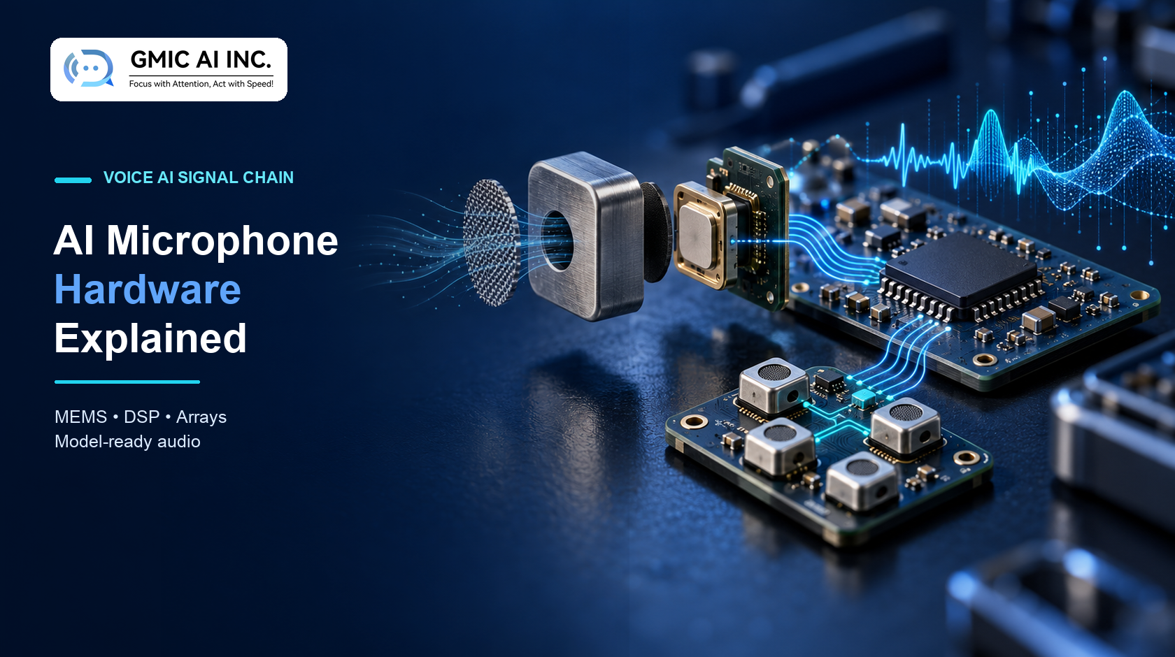
AI microphone hardware is the complete capture chain that turns acoustic pressure into audio a speech model can use reliably. The microphone element matters, but so do the port, enclosure, clock, power rail, codec or digital interface, DSP, buffering, transport and test method. A strong model cannot reconstruct speech that the hardware clipped, masked, dropped or never captured.
In brief: Define the application metric first. Select the microphone and interface for the real sound field. Preserve signal integrity through mechanical, electrical and digital stages. Then validate model-ready audio on production-intent hardware across representative speakers, distances, noise and device states.
Explore GMIC voice AI hardware development or discuss an AI microphone device.
What Is an AI Microphone?
An “AI microphone” is not a single component category. In practice, the phrase can describe:
- A microphone connected to an AI application.
- A microphone array with beamforming or direction finding.
- A voice-capture device with noise reduction, echo control and voice activity detection.
- A wearable or room device that streams audio to a phone or cloud model.
- Hardware that performs wake-word or speech inference locally.
- A complete endpoint with microphones, DSP, processor, wireless link, storage and firmware.
The useful engineering question is therefore not “Does this microphone have AI?” It is “What audio and metadata must this product deliver to the model, under which conditions and within which power, latency, privacy and cost limits?”
The Signal Chain From Sound to Model
| Stage | Main function | Common failure mode |
|---|---|---|
| Acoustic scene | Speech reaches the device | Distance, reverberation, noise or competing talkers reduce intelligibility |
| Port and enclosure | Admit sound while protecting the device | Occlusion, resonance, leakage or wind noise alters the signal |
| MEMS microphone | Convert pressure to analog or digital output | Self-noise, clipping, mismatch or contamination |
| Analog front end / digital interface | Condition or receive the microphone signal | Gain error, power noise, clock problems or channel swaps |
| DSP | Filter, suppress noise, cancel echo or combine channels | Artifacts, lost speech cues or excessive latency |
| Buffer and firmware | Frame and timestamp audio | Overflow, discontinuity or timing drift |
| Codec and transport | Compress, store or transmit audio | Packet loss, reconnection gaps or incompatible formats |
| Model interface | Normalize and deliver expected tensors or samples | Wrong rate, scaling, channel order or preprocessing |
Every handoff needs an interface contract. Record sample rate, bit depth, channel order, frame size, timestamp rules, acceptable discontinuity, gain convention and error behavior.
MEMS Microphone Specifications That Matter
Supplier data sheets contain many numbers, but several parameters strongly influence voice capture.
Signal-to-noise ratio
SNR describes the relationship between a reference acoustic signal and the microphone’s self-noise. Higher SNR can preserve quieter speech details, but it does not remove environmental noise. Infineon’s MEMS microphone guidance notes that SNR, acoustic overload point, frequency behavior, phase response and current consumption all matter in system selection.
Acoustic overload point
Acoustic overload point indicates the upper sound-pressure region before distortion becomes large under the supplier’s stated condition. A device near a loudspeaker, machinery or handling impact can exceed this range. Review the complete THD-versus-SPL behavior rather than a single headline number.
Sensitivity and tolerance
Sensitivity determines output level for a defined acoustic input. Channel-to-channel tolerance matters for arrays because gain mismatch can degrade spatial processing. Firmware gain correction can help only when the device has a controlled calibration method and enough signal headroom.
Frequency and phase response
Speech products need appropriate bandwidth, but “wider” is not automatically better. Mechanical design and DSP must preserve the bands that drive the application. For arrays and cancellation systems, phase matching and group delay can be as important as magnitude response.
Current and operating modes
Always-on devices may spend far more time listening for an event than recording full-band audio. Compare active, low-power and standby behavior, clock requirements and transition time. A low headline current is useful only if the mode still provides the performance the trigger requires.
Analog, PDM or I²S/TDM?
Analog microphones
An analog MEMS microphone requires biasing and an analog signal path into an ADC or codec. It can offer flexibility, but layout, gain, power-supply noise, grounding and converter performance become part of the result.
PDM microphones
Pulse-density modulation microphones output a one-bit digital stream driven by a clock. The processor or codec must decimate and filter that stream into PCM. PDM can simplify some analog concerns, but clock integrity, routing, decimation resources and channel timing still need engineering attention.
I²S or TDM digital microphones
PCM-output digital microphones can reduce downstream conversion work. TDM can carry several synchronized channels over shared lines. Confirm supported rates, word lengths, slots, clocking, startup behavior and processor peripheral limits.
Choose the interface as part of the complete architecture. A microphone is not “better” simply because its output is digital.
Sample Rate and Bit Depth: Match the Use Case
Sample rate defines the highest representable frequency after proper anti-alias filtering. Bit depth affects numeric resolution and headroom, but effective system performance is also limited by microphone noise, gain, converter quality and DSP scaling.
For speech applications, select the rate from model expectations, bandwidth, storage, transport, compute and quality requirements. Avoid unnecessary conversion stages. If a model consumes 16 kHz mono PCM, a 48 kHz array front end may still be justified for spatial processing, but the downsampling path must be defined and tested.
Arm’s CMSIS-DSP documentation illustrates that decimation combines low-pass filtering with sample-rate reduction; filtering before downsampling is necessary to prevent aliasing. This is a practical example of why format conversion is an engineering operation rather than a file-setting change.
Microphone Placement and Acoustic Ports
The final acoustic path includes port length, diameter, gasket, mesh, membrane, adhesive, cavity and wall thickness. Small mechanical changes can shift response or create variability.
Verify:
- Port alignment and assembly tolerance.
- Top-port versus bottom-port PCB and enclosure geometry.
- Leakage around gaskets and microphone bodies.
- Water- or dust-resistant membranes in the final stack.
- Clothing, finger and tabletop occlusion.
- Wind, breath, handling and structure-borne noise.
- Acoustic consistency after drop, aging and cleaning tests.
Use production-intent materials in acoustic validation. A 3D-printed opening without the final membrane does not prove the tooled design.
See GMIC’s AI audio front-end guide and custom enclosure design for AI hardware.
When Does a Microphone Array Help?
An array provides synchronized spatial samples that can support beamforming, direction-of-arrival estimation, echo control or source separation. It does not automatically improve recognition.
Array performance depends on:
- Microphone count and geometry.
- Spacing relative to target wavelengths.
- Gain and phase matching.
- Shared clock and channel synchronization.
- Enclosure scattering and port consistency.
- Source direction, distance and reverberation.
- DSP algorithms and tuning data.
A well-positioned near-field microphone may outperform an untuned array for a wearable device. A room product may justify several microphones because speaker distance and direction vary. Validate the architecture with the intended enclosure, not only an open development board.
Read the microphone array and beamforming hardware guide.
DSP Before the AI Model
The front-end pipeline may include high-pass filtering, equalization, automatic gain control, noise reduction, acoustic echo cancellation, beamforming, voice activity detection and sample-rate conversion. Each block changes the signal presented to the model.
More processing is not always better. Aggressive suppression can remove consonants or create musical artifacts. AGC can raise background noise during pauses. Echo cancellation needs a clean playback reference and correct delay alignment. Beamforming can fail when geometry or channel order is wrong.
Version DSP parameters with hardware, firmware and model versions. Preserve representative raw and processed recordings so a model regression can be separated from a capture regression. See AI DSP for voice devices and audio DSP tuning services.
Local Inference, Edge DSP or Cloud Processing?
| Architecture | Advantages | Constraints |
|---|---|---|
| Local trigger, cloud AI | Low-power wake or VAD with flexible cloud models | Requires a reliable transfer path after triggering |
| Edge preprocessing, cloud AI | Reduces bandwidth and improves capture consistency | DSP artifacts and parameter control affect model input |
| Full on-device inference | Lower network dependency and tighter data boundary | Compute, memory, power, thermal and update limits |
| Raw or lightly processed upload | Preserves information for server-side processing | Higher bandwidth, storage and privacy burden |
State exactly what “on-device AI” means. Wake-word detection, transcription, speaker identification and summarization have very different resource requirements.
Wireless Audio Is a System Choice
BLE can carry control messages and, in some architectures, audio data. Bluetooth LE Audio defines a standardized architecture using isochronous channels and the LC3 codec; the Bluetooth SIG describes LC3 as supporting 7.5 ms and 10 ms frames. That does not mean every BLE device or phone integration supports the same audio workflow.
Define codec, bitrate, framing, buffering, latency, retransmission or loss concealment, background application behavior and reconnection. Test phones and operating-system versions that represent the target fleet. For store-and-forward products, define acknowledgements and deletion rules so interrupted transfers do not silently lose or duplicate audio.
For implementation dependencies, see firmware integration for voice AI devices.
What Does “Model-Ready Audio” Mean?
Model-ready audio is a controlled interface, not a marketing adjective. Define:
- Sample rate, sample format and channel count.
- Expected full-scale convention and gain range.
- Frame length, overlap and timestamp behavior.
- DC removal, pre-emphasis or normalization.
- Raw versus processed channel availability.
- Missing-frame and packet-loss representation.
- Metadata such as device mode, DSP version and channel map.
- Privacy rules for storage, logs and test recordings.
Create reference files and automated checks. A pipeline should reject incompatible data rather than quietly resample, reorder or clip it without traceability.
Validate With Application Metrics
Electrical and acoustic measurements help diagnose the system, but product decisions should also use application-level results. A practical validation matrix can include:
- Speech recognition accuracy and critical-word errors.
- Wake-word false accepts and false rejects.
- Voice activity detection precision and missed speech starts.
- Speaker-distance and orientation performance.
- Single and competing talkers.
- Stationary, transient and nonstationary noise.
- Playback echo and double-talk.
- Packet loss, buffer pressure and reconnection.
- Battery, thermal and processor-load conditions.
Use repeatable fixtures and realistic recordings. Report conditions, sample size, software versions and uncertainty. Do not turn one laboratory percentage into a universal product claim.
Prototype and Production Test Strategy
Prototype builds should answer named risks. Early evaluation boards can compare microphone types and processing loads. Integrated prototypes must then expose enclosure, power, radio and firmware interactions.
For production, define tests that can detect the faults the line may introduce:
- Missing, blocked or contaminated microphone.
- Incorrect channel or clock configuration.
- Gain or frequency-response outlier.
- Port or gasket assembly error.
- Excessive noise or distortion.
- Wireless transfer and storage failure.
- Wrong firmware, DSP parameters or device identity.
Use controlled acoustic stimuli, calibrated references where required, fixtures, limits and traceable software versions. Golden units do not replace numeric acceptance criteria.
AI Microphone Hardware Selection Checklist
Before choosing a platform or manufacturer, confirm:
- Intended speakers, distance, noise and reverberation.
- Wearable, handheld, tabletop or room placement.
- Single microphone or synchronized array requirements.
- Analog, PDM, I²S or TDM interface and processor support.
- Sample formats required by DSP and model components.
- Wake-word, VAD, AEC, beamforming and noise-reduction ownership.
- Local, phone-mediated or cloud processing boundary.
- Storage, transport, offline and recovery behavior.
- Power, latency, thermal and memory budgets.
- Prototype, validation, certification and production-test evidence.
Frequently Asked Questions
Does an AI microphone need multiple microphones?
No. Multiple synchronized microphones enable spatial processing, but a single well-positioned microphone can be the better choice for a near-field product. Decide from the sound field, form factor and measured application result.
Is a digital MEMS microphone always better than an analog one?
No. Digital output can simplify parts of the signal path, while analog designs can offer useful flexibility. Performance depends on the selected component and complete electrical, mechanical and processing design.
What sample rate is best for voice AI?
There is no universal rate. Use the model’s input requirements, target bandwidth, DSP architecture, storage, transport and quality goals. Define any rate conversion explicitly and validate it.
Can noise reduction guarantee better transcription?
No. Noise reduction can improve some inputs but can also damage speech cues when it is too aggressive or mismatched to the noise. Compare raw and processed audio with application metrics across representative conditions.
Can Bluetooth carry AI microphone audio?
Yes, in suitable architectures, but control-only BLE, proprietary data transfer, Bluetooth Classic audio and LE Audio are different designs. Confirm phone support, codec, throughput, latency, power, loss recovery and background behavior.
Build the Capture Chain the Model Can Trust
AI microphone performance begins before inference. Treat acoustics, MEMS selection, electrical interfaces, DSP, firmware and transport as one controlled system. Preserve measurable requirements and reference data from prototype through production so model results remain explainable.
Talk with GMIC about an AI microphone hardware program.
Sources
- STMicroelectronics: MEMS Microphones Documentation
- Infineon: MEMS Microphones Electrical Implementation
- Infineon: MEMS Microphones in Noise-Cancelling Headsets
- Arm: CMSIS-DSP FIR Decimator Documentation
- Bluetooth SIG: LE Audio Specifications
- Bluetooth SIG: LC3 Specification
Editorial note: Technical guidance reflects public sources available on October 23, 2026. Component behavior and wireless support depend on the exact part, configuration, software and final product. Validate claims on production-intent hardware.